Those polished hubs are going to look real nice. Did the early bikes come that way?
S


honda305.com Forum
Vintage Honda Owners, Restorers, Riders and Admirers
1961 CB72 Project

Steve
The dual leading shoe brake in the background of one of my pics came to me covered in dirt. When I cleaned it up it looked pretty original and still has what appears to be its original lacquer (clear coat). I think that these parts, being die-cast just got a quick 'once over' with a polisher and then were clear coated to give them a little protection and sparkle.
I am going to try and re-produce that effect by polishing, then ultrasonically cleaning to get rid of the polishing compound and then clear-coating them. Don't want them to be too 'blingy'......
G
Steverino wrote:Those polished hubs are going to look real nice. Did the early bikes come that way?
S
'60 C77 '60 C72 '62 C72 Dream '63 CL72
'61 CB72 '64 CB77 '65 CB160
'66 Matchless 350 '67 CL77
'67 S90 '77 CB400F
'61 CB72 '64 CB77 '65 CB160
'66 Matchless 350 '67 CL77
'67 S90 '77 CB400F
I got the eBay 'spare' crank back together yesterday and had to sort out some decent rods for it after the originals were unusable.
It's interesting how many variations -both OEM and aftermarket - there are. On the right here is a pattern rod which has not got the oil slots made properly. The '12 O'clock" position should have a complete slot which squirts escaping oil from the big-end up toward the piston and small end, like the one on the left.

And here is an early Dream rod where the oil squirts out at 12 O'clock, 4 O'Clock and 8 O'clock. I'm not too sure where that oil goes to but the design doesn't seem to have lasted.

In the end I thought I'd use up those aftermarket rods and open up the 12 O'clock slit just to keep the oil moving in the right direction to cool the piston and lube the small end.

This isn't the prettiest crank around but I know that it has fresh bearings and clear oilways. That isn't graranteed for all cranks coming off eBay. The situation can only get worse as the good ones get used up.


It looks like I shall be able to build two decent cranks out of the three that I bought so that seems fair.
This is what this one looked like before I started...

G
It's interesting how many variations -both OEM and aftermarket - there are. On the right here is a pattern rod which has not got the oil slots made properly. The '12 O'clock" position should have a complete slot which squirts escaping oil from the big-end up toward the piston and small end, like the one on the left.
And here is an early Dream rod where the oil squirts out at 12 O'clock, 4 O'Clock and 8 O'clock. I'm not too sure where that oil goes to but the design doesn't seem to have lasted.
In the end I thought I'd use up those aftermarket rods and open up the 12 O'clock slit just to keep the oil moving in the right direction to cool the piston and lube the small end.
This isn't the prettiest crank around but I know that it has fresh bearings and clear oilways. That isn't graranteed for all cranks coming off eBay. The situation can only get worse as the good ones get used up.
It looks like I shall be able to build two decent cranks out of the three that I bought so that seems fair.
This is what this one looked like before I started...
G
Last edited by G-Man on Tue Oct 06, 2015 2:07 am, edited 2 times in total.
'60 C77 '60 C72 '62 C72 Dream '63 CL72
'61 CB72 '64 CB77 '65 CB160
'66 Matchless 350 '67 CL77
'67 S90 '77 CB400F
'61 CB72 '64 CB77 '65 CB160
'66 Matchless 350 '67 CL77
'67 S90 '77 CB400F
-
LOUD MOUSE
- honda305.com Member
- Posts: 7818
- Joined: Mon Aug 15, 2005 8:23 am
- Location: KERRVILLE, TEXAS
<squirts escaping oil from the big-end up toward the piston and small end>
G may I ask where this idea came from?
As any engine runs OIL IS GOING TO ALL CORNERS as the internal parts are rotating at good RPM'S.
Yes under pressure there are parts which get INTERNAL oiling.
Ever though that like many parts of these bikes had mfg. changes as more parts were needed and HONDA ordered from the best source as to the $$$ on that part?
Take the time to show any data about the design of the BIG END that actually makes a difference as I see that area as nothing other than a place for the crank to rotate and the oil under no pressure other than SPLASH OIL to lube the BIG END. (rod pin doesn't have a hole through the center) Same for the LITTLE end except some have round holes and early issue have cut slots..
As I know the crank, the part which gets oil by Pressure is the right crank bearing and the centers get oil from the top as the engine splashes oil.
Of course the cam followers/rockers and other parts in the top area get oil under pressure and splash.
As I started this QA do show me where you have the data and I'll get on board with ya. .........lm
G-Man wrote:I got the eBay 'spare' crank back together yesterday and had to sort out some decent rods for it after the originals were unusable.
It's interesting how many variations -both OEM and aftermarket - there are. On the right here is a pattern rod which has not got the oil slots made properly. The '12 O'clock" position should have a complete slot which squirts escaping oil from the big-end up toward the piston and small end, like the one on the left.
squirts escaping oil from the big-end up toward the piston and small end
LM - Good questions.
Although the centre main bearings are indeed fed from oil descending from above, they also have a direct feed from the oil gallery at the front of the engine, getting fresh oil straight from the filter before it gets to the top of the engine. The main bearings are internally ported to direct oil sideways in to a pair of 'oil slingers" (centrifuges) which feed oil into a gallery in the centre of each big end. The hole you can see at around 10 O'clock is the hole into the hollow big-end pin. I have removed the aluminum plug at the outer end to clean the gallery.

As this rotates, oil is flung outwards, boosting the pressure feed to the big end, via two oilways in the big end pin. Just like you swung a bucket of water over your head as a kid, and it didn't run out, the oil is 'forced' into the big end bearing. The pressure (force generated on the oil) depends on the diameter of the annular gallery in the flywheel and the rotational speed of the engine.
F = 'mass' x 'radius of centrifuge' x 'rotational speed squared'
More speed equates to more pressure at the bearing providing we don't let the oil escape too quickly and providing we can get enough in via the main bearing oil feed. Doubling the speed increases the pressure by four times. These galleries also work as a centrifugal oil filter, collecting sludge, as the 'mass' of dirt particles will normally be greater than the oil around it. The hardness of this sludge and the way it gets packed in is a testament to the forces generated in that centrufugal oil slinger slot.
https://encrypted-tbn2.gstatic.com/imag ... Pvkdtd4MhA
Below you can see the outer end of the hollow big-end pin. Also visible is one of the two holes that feed oil to the surface of the big-end at 10 and 2 O'clock.

Here is a pic of the main bearing oil feeds into the centrifuge in the flywheel.

That ring with the little holes in nestles right inside the centrifuge and the centrifuge has a rim to trap the oil so that it goes toward the big end in preference to leaking straight back out. Those little holes are always blocked with sludge in the cranks I have stripped (5 or 6 recently) and have to be physically poked out.

Just like a pressure-fed big end (although we are talking lower pressures) the oil has to escape somewhere. If there are no slots in the faces of the con-rod big-end, the oil will escape evenly around the sides of the rod. But you can choose to be selective in where the oil goes by creating slots that run right to the edge of the side face as in the later Honda rods.
That 12 O'clock slot, is always pointing to the underside of the piston and the small end. The piston will be hotter than the crank so the oil going in that direction will have a small cooling effect but it will also get to the top side of the rod and get into the oil slots / holes.
I noticed on my shell-bearing (pressure-fed) CB400F crank and rods that there are oil holes on top and bottom of the little end eye, as well as one in the rod, which set me looking at the CB72 cranks and rods.
Yes there will be a quantity of oil being thrown off the flywheels but that will naturally go in all directions and gravity will play a part. The separators in the bottom are continually skimming that as the crank rotates.
I think that this is a clever piece of crankshaft design for a high-revving engine. It took a while to get the rod / big-end design sorted. The very early Dream engines only had 25mm crank pins with 3mm rollers and bronze cages but that soon got changed to the 26mm pin with 2.5mm rollers and aluminum cages.
G
Although the centre main bearings are indeed fed from oil descending from above, they also have a direct feed from the oil gallery at the front of the engine, getting fresh oil straight from the filter before it gets to the top of the engine. The main bearings are internally ported to direct oil sideways in to a pair of 'oil slingers" (centrifuges) which feed oil into a gallery in the centre of each big end. The hole you can see at around 10 O'clock is the hole into the hollow big-end pin. I have removed the aluminum plug at the outer end to clean the gallery.
As this rotates, oil is flung outwards, boosting the pressure feed to the big end, via two oilways in the big end pin. Just like you swung a bucket of water over your head as a kid, and it didn't run out, the oil is 'forced' into the big end bearing. The pressure (force generated on the oil) depends on the diameter of the annular gallery in the flywheel and the rotational speed of the engine.
F = 'mass' x 'radius of centrifuge' x 'rotational speed squared'
More speed equates to more pressure at the bearing providing we don't let the oil escape too quickly and providing we can get enough in via the main bearing oil feed. Doubling the speed increases the pressure by four times. These galleries also work as a centrifugal oil filter, collecting sludge, as the 'mass' of dirt particles will normally be greater than the oil around it. The hardness of this sludge and the way it gets packed in is a testament to the forces generated in that centrufugal oil slinger slot.
https://encrypted-tbn2.gstatic.com/imag ... Pvkdtd4MhA
Below you can see the outer end of the hollow big-end pin. Also visible is one of the two holes that feed oil to the surface of the big-end at 10 and 2 O'clock.
Here is a pic of the main bearing oil feeds into the centrifuge in the flywheel.
That ring with the little holes in nestles right inside the centrifuge and the centrifuge has a rim to trap the oil so that it goes toward the big end in preference to leaking straight back out. Those little holes are always blocked with sludge in the cranks I have stripped (5 or 6 recently) and have to be physically poked out.
Just like a pressure-fed big end (although we are talking lower pressures) the oil has to escape somewhere. If there are no slots in the faces of the con-rod big-end, the oil will escape evenly around the sides of the rod. But you can choose to be selective in where the oil goes by creating slots that run right to the edge of the side face as in the later Honda rods.
That 12 O'clock slot, is always pointing to the underside of the piston and the small end. The piston will be hotter than the crank so the oil going in that direction will have a small cooling effect but it will also get to the top side of the rod and get into the oil slots / holes.
I noticed on my shell-bearing (pressure-fed) CB400F crank and rods that there are oil holes on top and bottom of the little end eye, as well as one in the rod, which set me looking at the CB72 cranks and rods.
Yes there will be a quantity of oil being thrown off the flywheels but that will naturally go in all directions and gravity will play a part. The separators in the bottom are continually skimming that as the crank rotates.
I think that this is a clever piece of crankshaft design for a high-revving engine. It took a while to get the rod / big-end design sorted. The very early Dream engines only had 25mm crank pins with 3mm rollers and bronze cages but that soon got changed to the 26mm pin with 2.5mm rollers and aluminum cages.
G
Last edited by G-Man on Tue Oct 06, 2015 5:26 am, edited 5 times in total.
'60 C77 '60 C72 '62 C72 Dream '63 CL72
'61 CB72 '64 CB77 '65 CB160
'66 Matchless 350 '67 CL77
'67 S90 '77 CB400F
'61 CB72 '64 CB77 '65 CB160
'66 Matchless 350 '67 CL77
'67 S90 '77 CB400F
Following on from the previous post - this is the honda oil circulation diagram, showing that the crank gets fresh oil pumped directly from the filter and that the next port of call from the big end is the small end. In the key to their diagram, Honda call this feed to the small end a 'direct' feed.
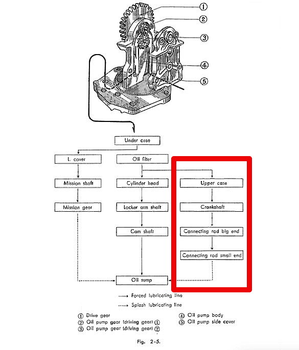
The oil from the filter goes into the oil gallery at the front of the upper crankcase and from there goes two ways. Either up the front two corner studs (joined by the oil gallery in the barrel) to the top end, OR, to the front oil holes in the main bearings where it is directed into the mains and sideways into the big ends.
The '9th hole' in the barrel flange connectes straight through to the left (front drilling) main bearing feed.

It also joins up with this channel which connects the pressure feed from the left bearing to the right one, again at the front drilling.

The centre hole in the mains is connected to small oil reservoirs in the top crankcase half. These collect oil coming down from the valve gear. This is not filtered oil but has not really been anywhere particularly dirty and does not get forced to the big end.

Interestingly, only one of the oil 'side' jets in each main bearing gets the oil from the oil filter. The back one is blocked in each case. This, I suppose, eliminates the need for 'handed bearings'.

So, the big ends get force-fed fresh oil from the pump / filter as well as a little bit of splash. The oil that enters the inner flywheel annuli is boosted by centrifugal force up into the big end and onward up to the piston / small end. All good reason to keep your pump / filter and all oilways clean and clear. Also, when rebuilding a crank, perhaps a good reason for keeping rod side clearance relatively small to keep the oil flowing upwards.......
G
The oil from the filter goes into the oil gallery at the front of the upper crankcase and from there goes two ways. Either up the front two corner studs (joined by the oil gallery in the barrel) to the top end, OR, to the front oil holes in the main bearings where it is directed into the mains and sideways into the big ends.
The '9th hole' in the barrel flange connectes straight through to the left (front drilling) main bearing feed.
It also joins up with this channel which connects the pressure feed from the left bearing to the right one, again at the front drilling.
The centre hole in the mains is connected to small oil reservoirs in the top crankcase half. These collect oil coming down from the valve gear. This is not filtered oil but has not really been anywhere particularly dirty and does not get forced to the big end.
Interestingly, only one of the oil 'side' jets in each main bearing gets the oil from the oil filter. The back one is blocked in each case. This, I suppose, eliminates the need for 'handed bearings'.
So, the big ends get force-fed fresh oil from the pump / filter as well as a little bit of splash. The oil that enters the inner flywheel annuli is boosted by centrifugal force up into the big end and onward up to the piston / small end. All good reason to keep your pump / filter and all oilways clean and clear. Also, when rebuilding a crank, perhaps a good reason for keeping rod side clearance relatively small to keep the oil flowing upwards.......
G
'60 C77 '60 C72 '62 C72 Dream '63 CL72
'61 CB72 '64 CB77 '65 CB160
'66 Matchless 350 '67 CL77
'67 S90 '77 CB400F
'61 CB72 '64 CB77 '65 CB160
'66 Matchless 350 '67 CL77
'67 S90 '77 CB400F
-
LOUD MOUSE
- honda305.com Member
- Posts: 7818
- Joined: Mon Aug 15, 2005 8:23 am
- Location: KERRVILLE, TEXAS
I'm on my way to BARBER and will read your reply when I return.
A quick look still didn't seem to explain your idea that any real amount of oil is sent to the bottom of the piston from the design of the big end of the rod.
I didn't include the oil path to the center bearings as that is very visible as one looks at the cases and outer race of the center bearings.
I'm respond more when I return. ...............lm
G-Man wrote:LM - Good questions.
Although the centre main bearings are indeed fed from oil descending from above, they also have a direct feed from the oil gallery at the front of the engine, getting fresh oil straight from the filter before it gets to the top of the engine. The main bearings are internally ported to direct oil sideways in to a pair of 'oil slingers" (centrifuges) which feed oil into a gallery in the centre of each big end. The hole you can see at around 10 O'clock is the hole into the hollow big-end pin. I have removed the aluminum plug at the outer end to clean the gallery.
As this rotates, oil is flung outwards, boosting the pressure feed to the big end, via two oilways in the big end pin. Just like you swung a bucket of water over your head as a kid, and it didn't run out, the oil is 'forced' into the big end bearing. The pressure (force generated on the oil) depends on the diameter of the annular gallery in the flywheel and the rotational speed of the engine.
F = 'mass' x 'radius of centrifuge' x 'rotational speed squared'
More speed equates to more pressure at the bearing providing we don't let the oil escape too quickly and providing we can get enough in via the main bearing oil feed. Doubling the speed increases the pressure by four times. These galleries also work as a centrifugal oil filter, collecting sludge, as the 'mass' of dirt particles will normally be greater than the oil around it. The hardness of this sludge and the way it gets packed in is a testament to the forces generated in that centrufugal oil slinger slot.