- 1) Needle was doing fine as I was accelerating, but as I slowed down the needle stayed indicating I was moving at high speed
2) As I sped up again, the needle kept moving upward, and almost maxed the speedo out.
3) The needle would come to rest at 0 after a long time.
Then one day the needle just didn't move at all. Uh-oh I thought, it's time to GET MY HANDS DIRTY.
First, unscrew this bolt underneath your headlamp

You'll see a jumble of wires. I balanced my headlight on the front fender. It's probably best to disconnect it so it doesn't fall and break. Take out the small lightbulbs. You have to push them in and turn to get them out.

Now you can unscrew the speedometer cable from the speedo housing and the bracket holding the speedo to the headlight bucket.

All done!

Now the whole unit pops out of the top. There will probably be white crumbly stuff that cracks away. It is some sealant that we'll replace.


Now the MOST ANNOYING PART. You have to bend the bezel up with meticulous carefulness. I used a small flat head to continually pry around the edges. This probably to me upwards of 6 HOURS because I was being so careful.


After a very long time, I got it apart! Here is the bezel, glass face, and inner bezel separated from the speedo:

Now to get the inner assembly out, turn the speedo over and unscrew these fools:

Tada! Speed inner assembly is out. I had a lot of rust. My next step was to soak it in brakleen. This would dissolve any oils inside of the rotating cap/cup. Looking back, I probably didn't have to do this because mine was BONE DRY. I put nuts in the cup to take up space so I didn't have to use as much brakleen.


After cleaning:

And Oh $H!T The brakleen ate the paint / numbers off of my face plate. Word of caution: take off the plate before you soak it! Oh well, you live an learn.

These screws take off the face plate

You'll also have to get the needle off. I used a spoon. Carefully pry up on each side, working your way around. It will pop off you'll swear that you broke it. You didn't.


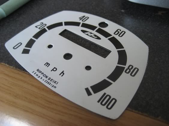
So what I did to remedy my crappy faceplate was order a sticker from stickers@reproductiondecals.com. You have to e-mail them and ask them because it's a secret menu item, like animal style (any californians?). It was $16. The down side is that there is no hole for the high beam indicator.
Here's pictures of my procedure. I bought black spray paint.


The sticker does a great job of sticking to the paint! But I didn't prime the metal, so the paint came right off (mess up #2!)! I just epoxied it on and it was fine. Make sure you prime the metal plate. Now onto the speedo mechanisms. Something wasn't allowing these gears to turn.
I wanted to clean / sand all the rust off of the gears, so I unscrewed these screws:


Now I could clean these gears. But still the numbers wouldn't turn. Whatever it was it even snapped a tooth off of my numbers!

It turns out that the numbers had locked up for some reason. So, thanks to the members here I was sent another number assembly. For those who are curious, here are some pictures of the core components of the odometer.

To get the odometer out, you need to pull out a brass clip which rides the shaft going through the odometer. Then with the greater amount of play you've created by taking out this clip you can move this brass bearing out of its hole and closer to the odometer. Then you can finagle the odometer out.


Once my numbers were restored, I put the parts back together and then oiled it up with this clipper oil on all the moving parts. You should use VERY LIGHT OIL. All others will be too viscous.


After this I reassembled some of it and calibrated my speedo. I also made a mini-ghetto gasket out of an old bike tire to go in between the bucket and the speedo so it wouldn't vibrate a lot.


White Russian break

Back at it
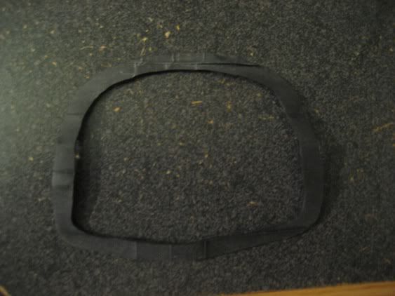
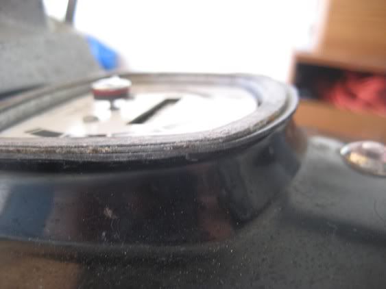
Test set up!
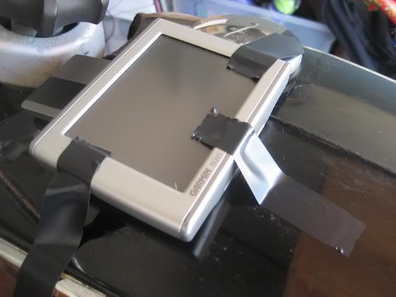
What I found was that my needle was moving way high again! This meant there was too much oil in the place where the inverted cup rotates in the other cup. Circled below
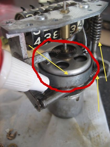
I snuck some tissue paper in between the two cups and soaked up all the oil I could. I pretty much got all out all the oil that was possible, and then the calibration was correct when comparing my GPS to my needle. You can also rotate the needle so that 0 starts lower / higher than 0 on the face. This might help with the calibration as well.
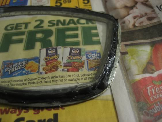
Now to begin putting it all back together. I first got some gasket epoxy (~$6-$8) and rubber cement from ace hardware. I cut another gasket from the bike inner tube, and used the contact cement to mate it with the inner bezel. The trick here is that you should not see the rubber gasket when you place the inner bezel back into the outer bezel. It takes some trimming, but it is worth it.
Then I placed the glass on top of this.
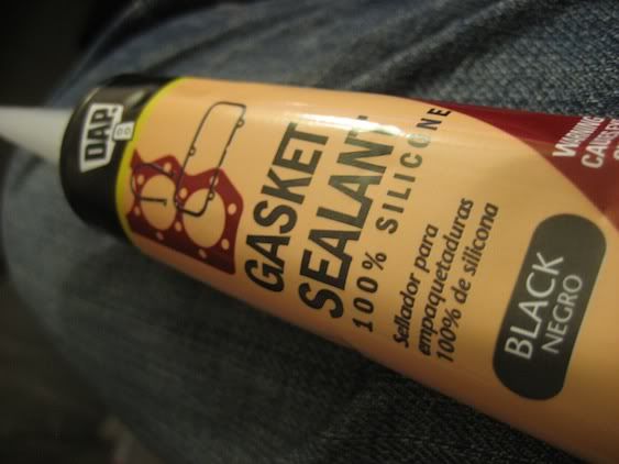
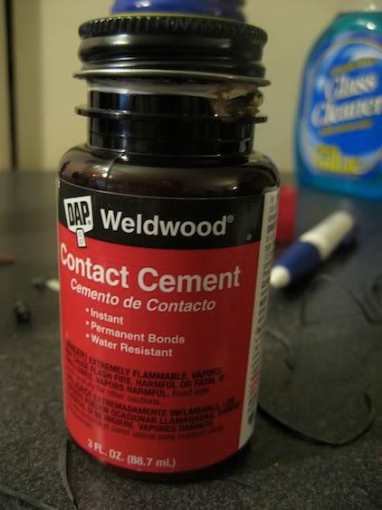
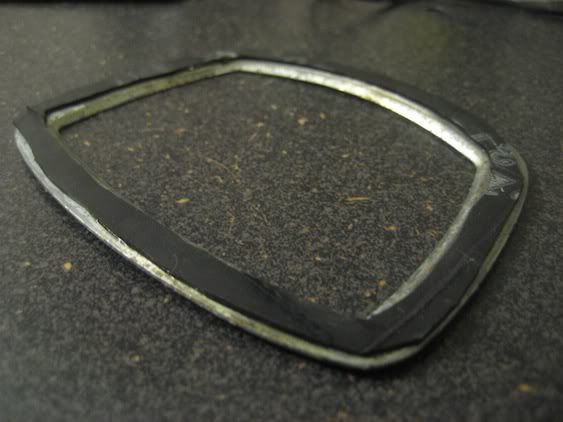
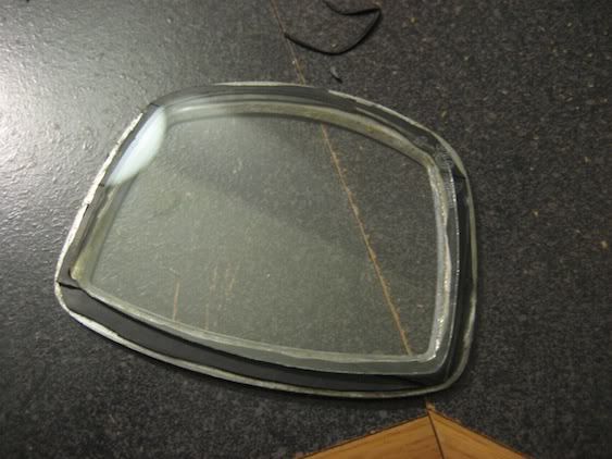
Now put a bead of the silicone around the glass, gasket, and inner bezel.
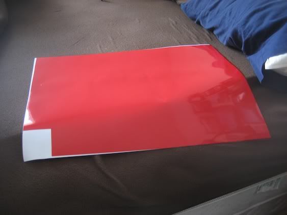
Before moving on, I wanted to fix up my high-beam indicator. I cut a hole in the sticker.
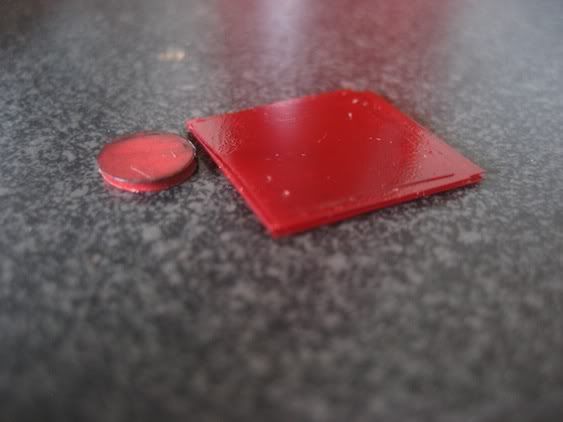
The brakleen has also messed up the little red plastic piece that the light shined through. So I bought some thing red plastic, cut it up, epoxied it together, and put it on the back of the face plate. If anyone needs any of this stuff, I've got a lot left.
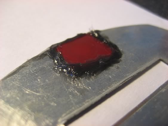
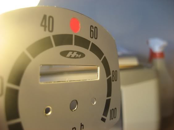
After this was done, I put a lot of the gasket sealant in the outer bezel. Then you just have to press it back on and watch all the goop spill out. Don't worry, you can clean it off using a razor blade, windex. Just don't scratch the glass!
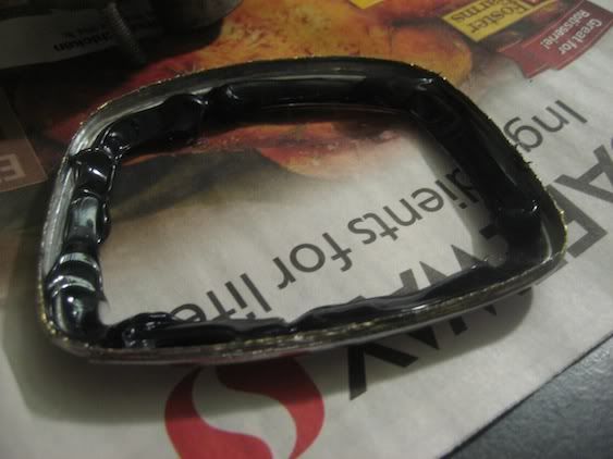
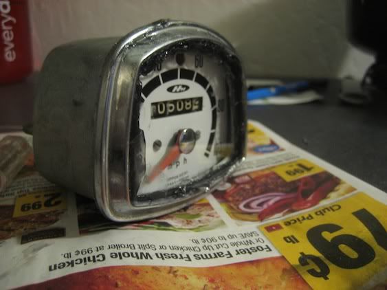
Mine got hard to press on really far, so I didn't get to crimp down the bezel as much as it originally was. I also didn't put any liquid gasket type material around the speedo mount on the Dream, because I wanted to be done. I just kept the rubber gasket I had for calibrating the speedo.
Turns out because the numbers weren't turning, it snapped the inner speedo cable, so I had to but a new one from OhioCycle. I got it, put it in the outer casing, reattached the speedo cable to the worm gear on the front tires, and put the speedo back together
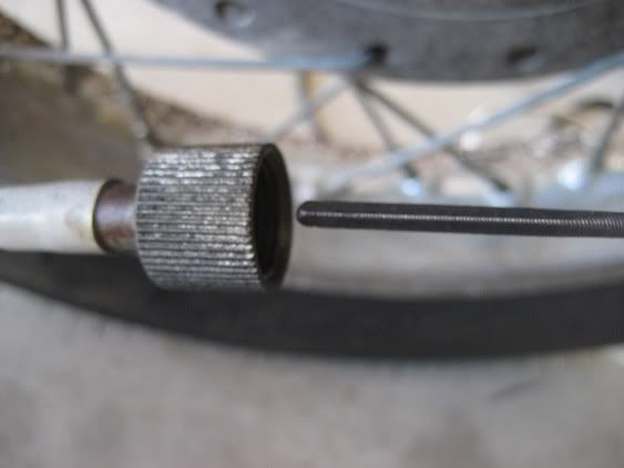
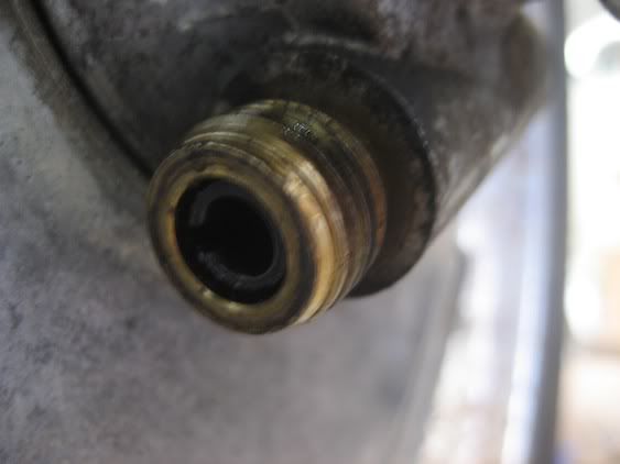
And it works! The only thing I have noticed is that the backlighting from one of the lights might not be able to get through one of the sides. Not sure what is blocking it...maybe some silicone or something. So that is my adventure. Here are some threads that helped me get through this process. Good luck if you try it yourself!
CL Speedometer Rebuild
Speedometer reads twice as fast
Speedometer needle removal
Speedo Calibration
Speedo pegged and died


